Specification Review
Review fixture schedules, BOQ, CAD, protocol, voltage, certification and existing control requirements.
 计时中
计时中

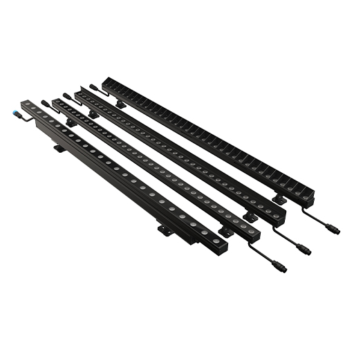
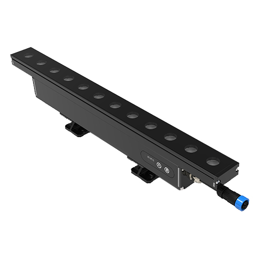
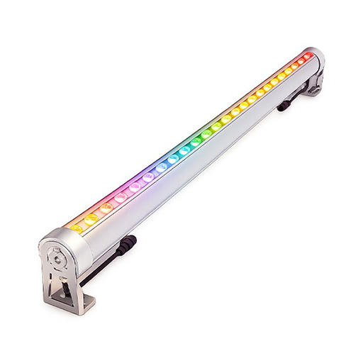
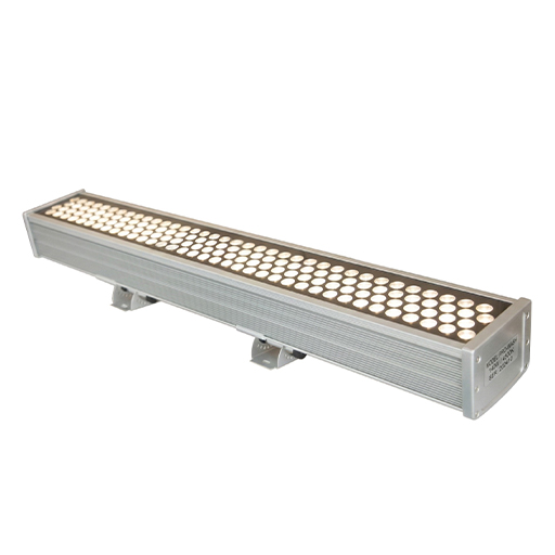
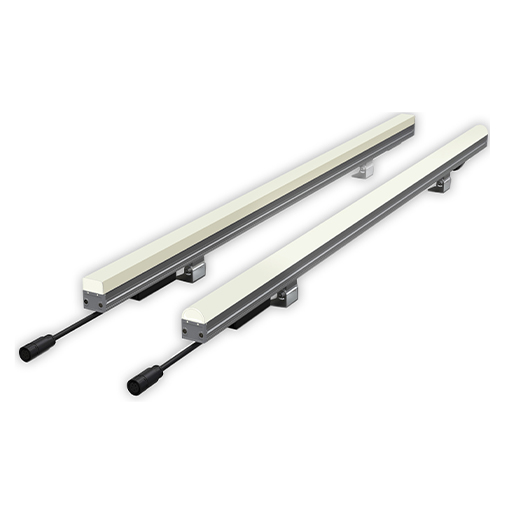
LWW-PZT-W38A
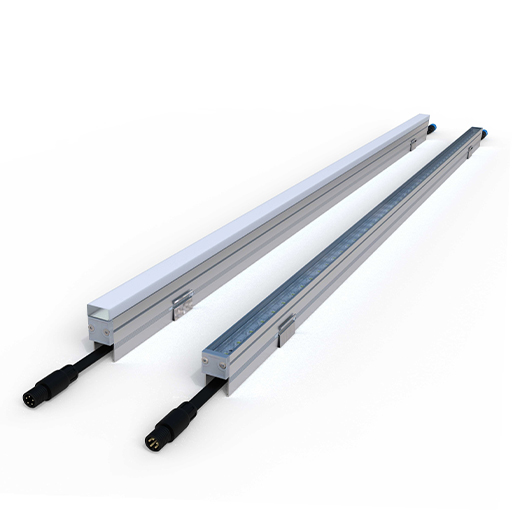
LWW-WZB-W55
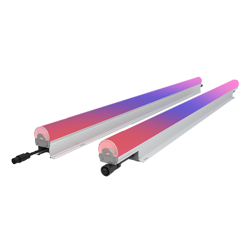
LWW-OP-D80
LWW-ROWS-W150
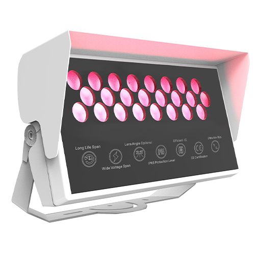
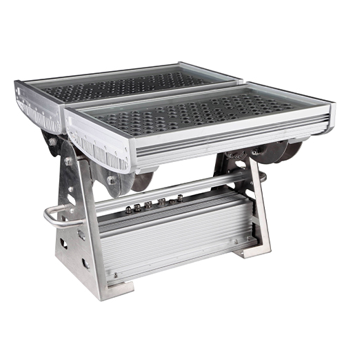
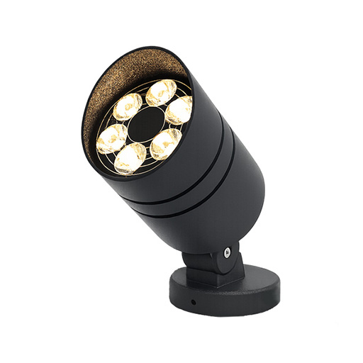
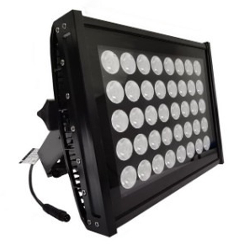

SP-DKP-F170A
SP-MEGA-F620A
SP-MEGA-F310A/B
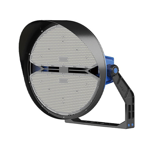
STD-YXYSW4
STD-YXYSW5
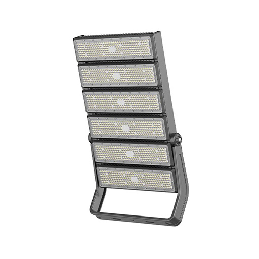
STD-YXYSW6
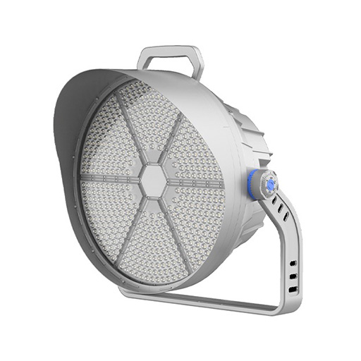
STD-YXYDF3A
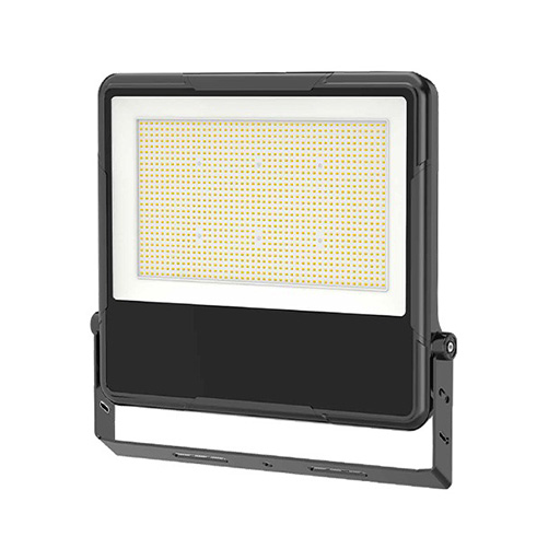
LLS-WZB-W40
LLS-OP-W30A
LLS-OP-W20
LLS-OP-D50
SP-EA-R195/R225
Jinyun County
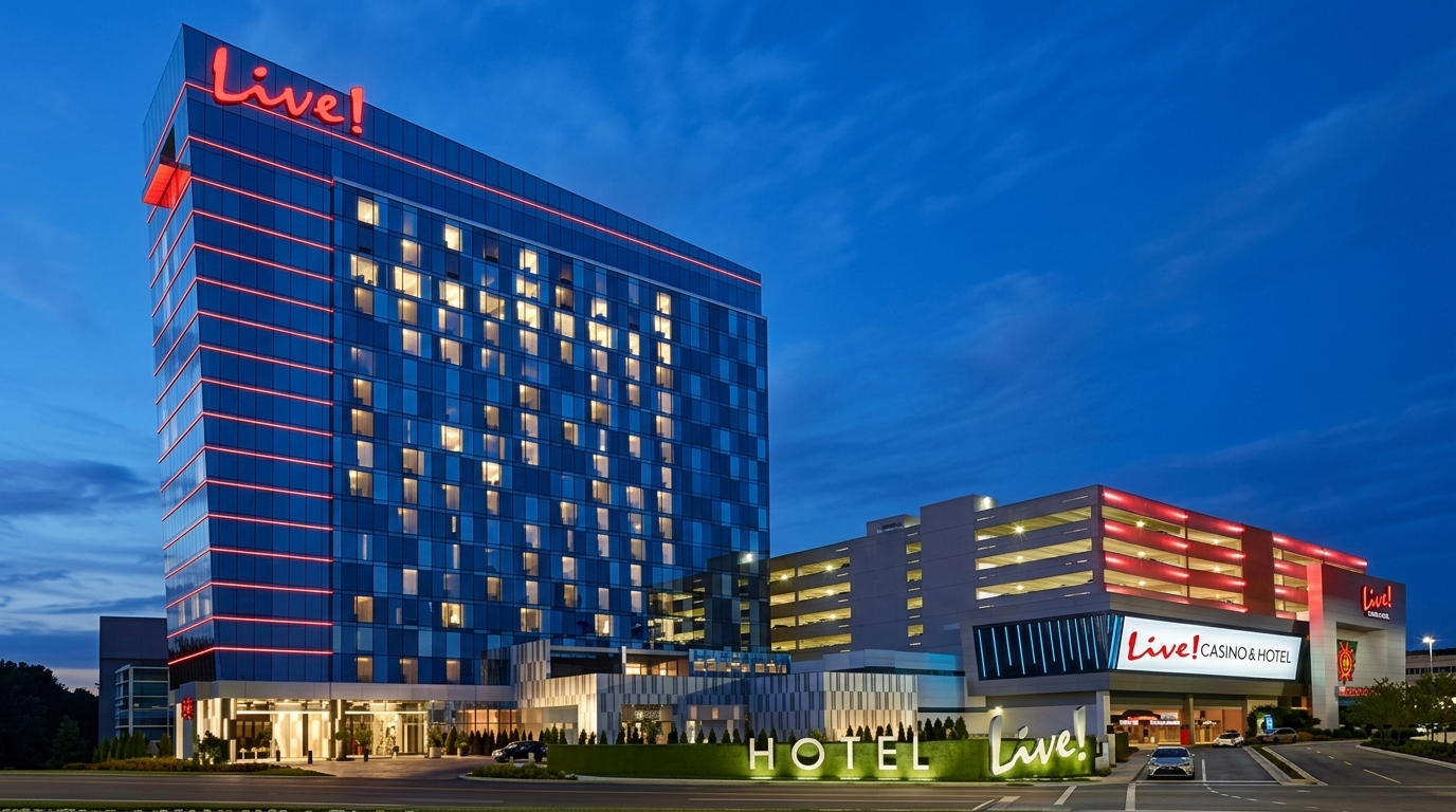
Live Hotel
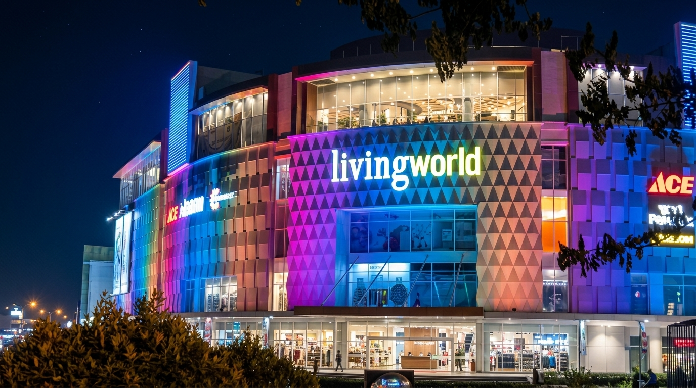
Living World Mall Indonesia
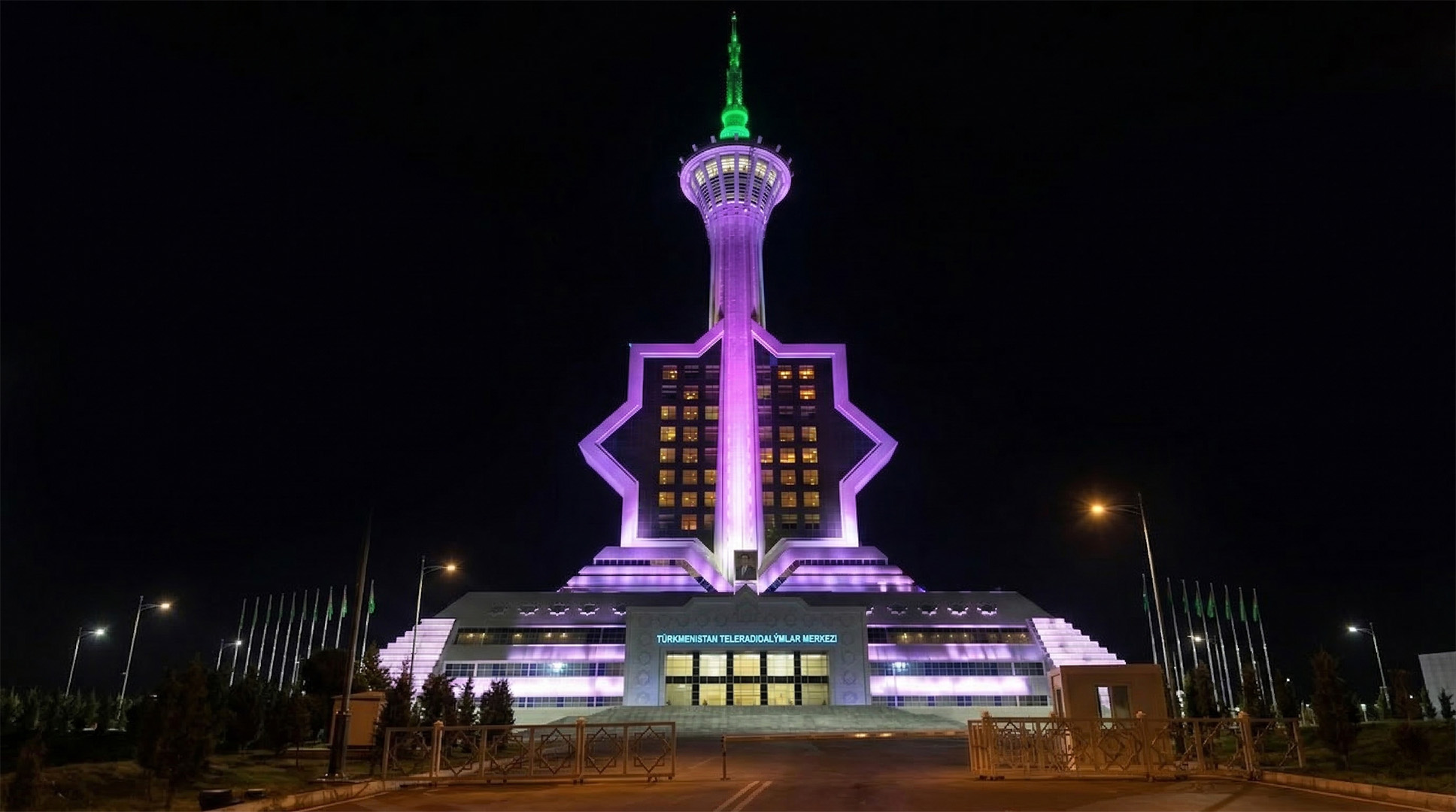
Turkmenistan Engineering
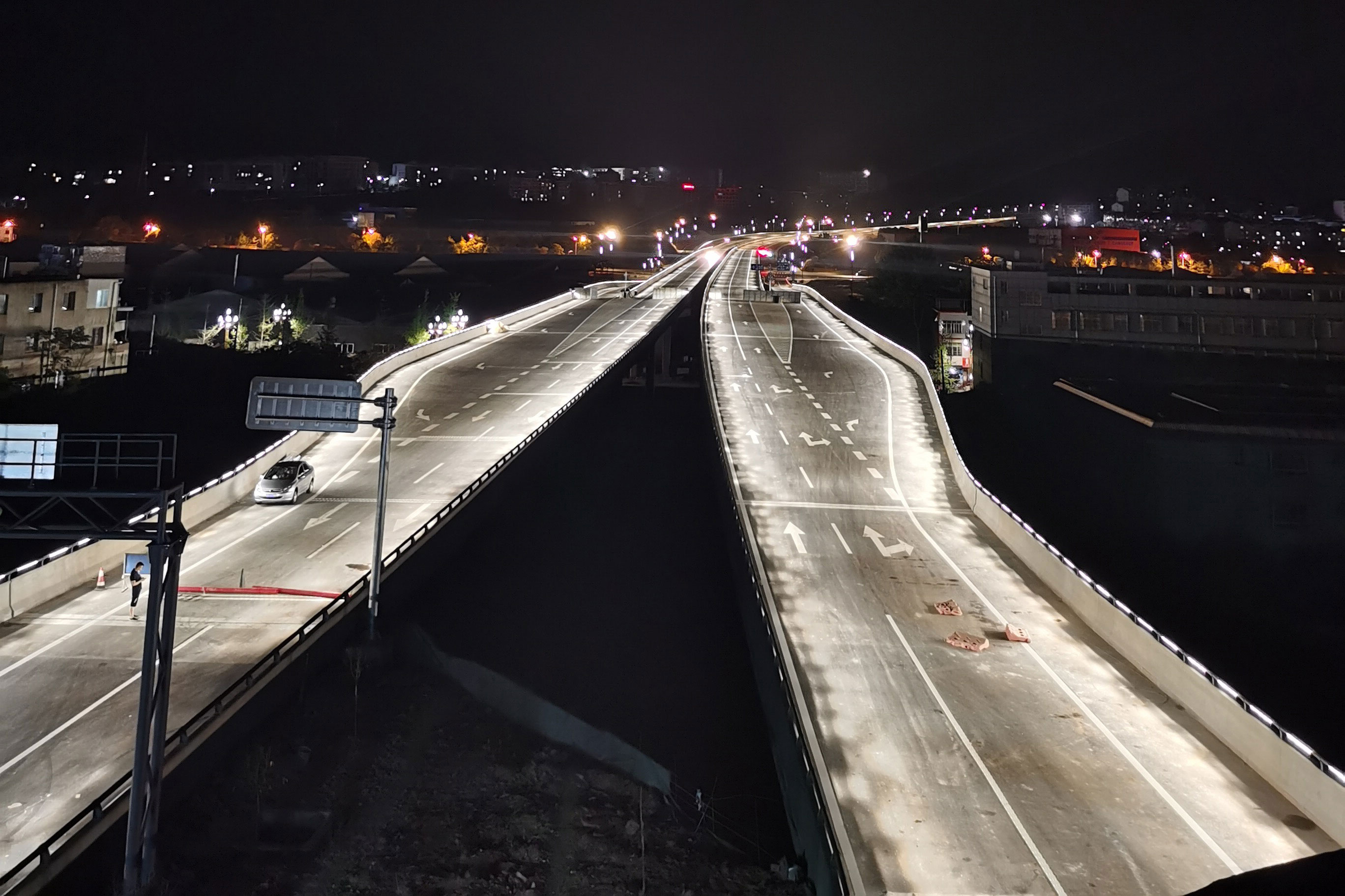
Mianyang city a ring road overpass
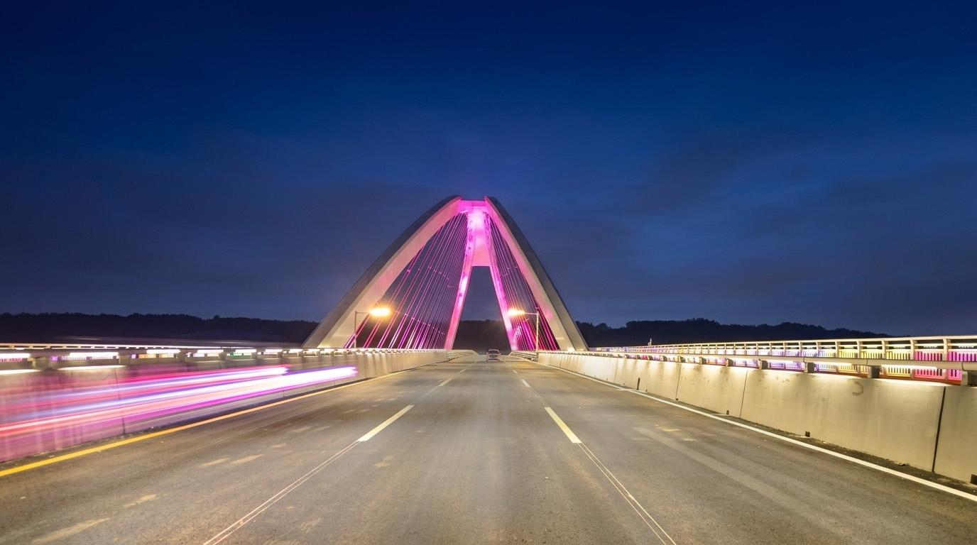
Lighting Project of Fujiang Bridge

The volga river bridge

Road Lamp Project of Nanlang Village
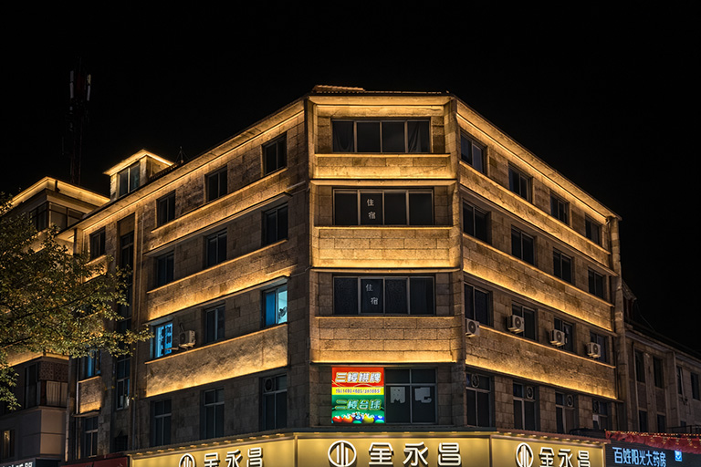
Kleanthis Vikelidis Stadium
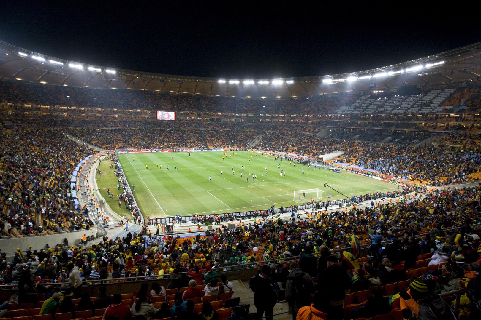
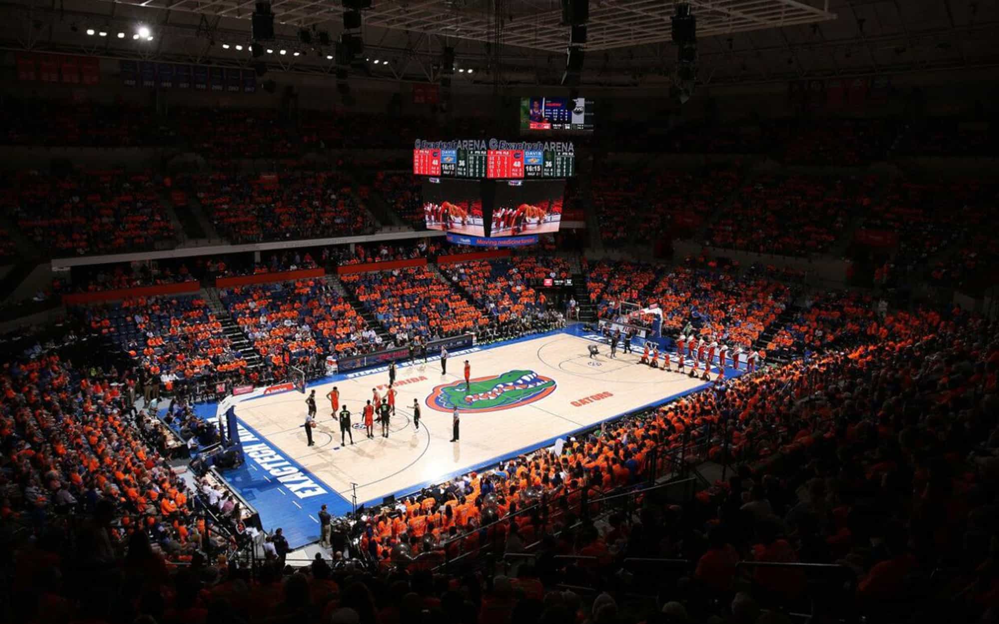
Florida Atlantic University

Shahid Nassiri Stadium

Rangers Ballpark
TPK manufactures the luminaires and helps engineering teams put the control package around them. From controller architecture and universe sizing to wiring drawings, addressing, factory system tests and remote commissioning support, we help turn a lighting specification into a control system that can actually be installed and checked on site.
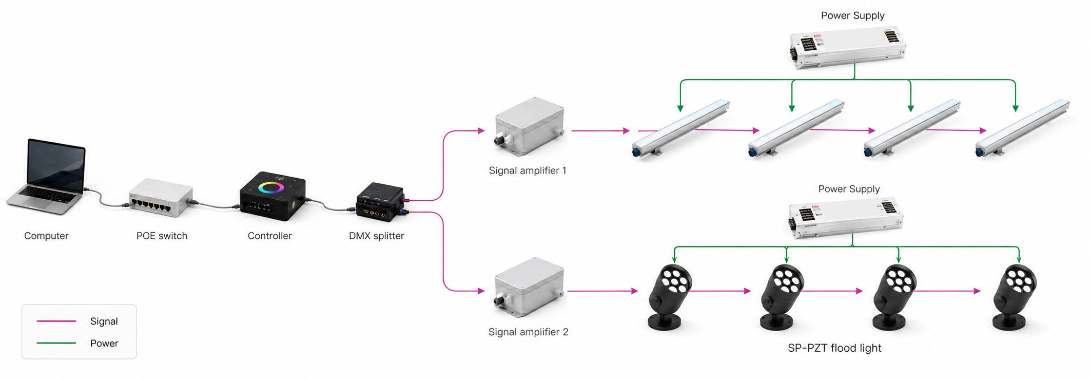
If your consultant or client has already specified Color Kinetics, Lumenpulse, Pharos, MADRIX or another DMX/eDMX-based solution, send us the specification, fixture schedule and project drawings. We can review the control requirements, propose compatible TPK luminaires and build the required control, signal and accessory package around the project.
Review fixture schedules, BOQ, CAD, protocol, voltage, certification and existing control requirements.
Size controllers, universes, ports, nodes and the network path from the actual fixture schedule.
Plan splitters, amplifiers, connectors, cable routes, termination and signal accessories.
Prepare addresses, mapping, agreed scenes and system-level factory verification where required.
Provide drawings, BOM, address schedules, configuration backups, installation notes and test records.
Support start-up, addressing, signal checks, software recognition and fault isolation remotely.
You do not need to redesign the project before asking TPK for a quotation. Send the consultant specification, fixture schedule and drawings you already have; we identify what is complete, what still needs clarification and what the control package must include.
Color Kinetics, Lumenpulse, Pharos, MADRIX or another DMX/eDMX-based requirement can be used as the starting point.
Quantity, RGB/RGBW/pixel mode and channels per fixture drive the universe and port calculation.
CAD, elevation or marked-up plan helps us place controllers, nodes and signal routes before the site is closed.
Call out project voltage, ETL/cETL or other luminaire requirements and any existing controller platform.
Competitor or consultant specification, BOQ, CAD/elevation, fixture count, channel mode, voltage, certification requirement and existing controls.
Protocol, channel load, project zones, topology, signal route, control distance, accessory requirements and existing-system compatibility.
Control path, controller/node sizing, principle drawing, accessory BOM, address plan and factory/handover scope.
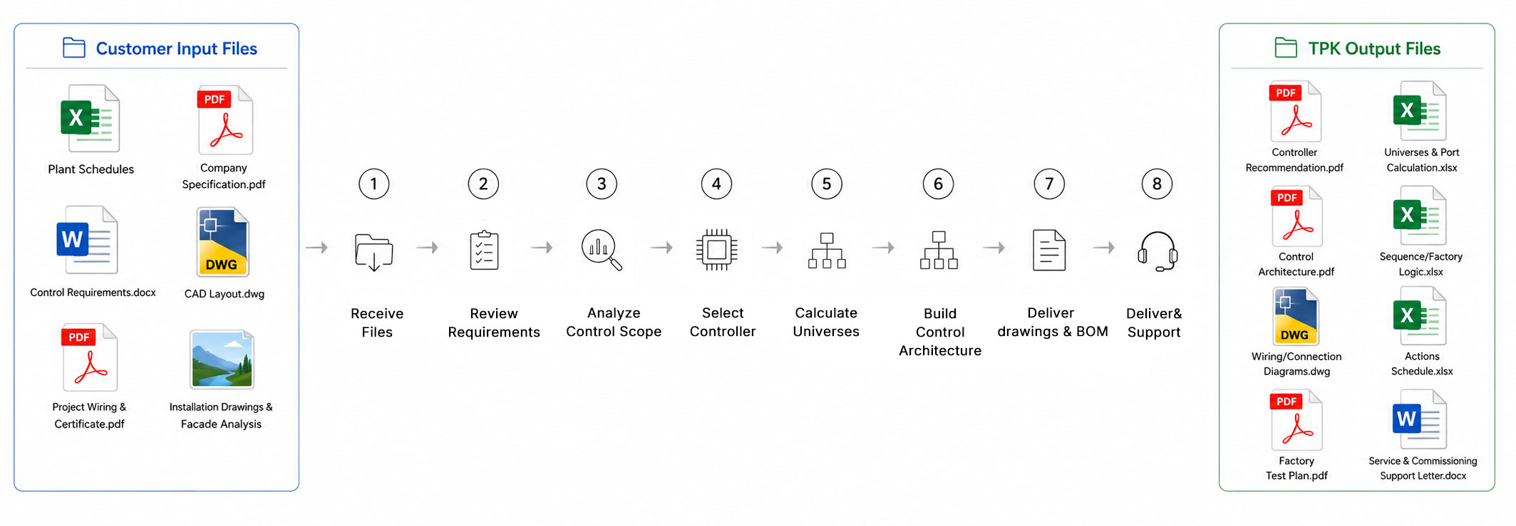
Fixture quantity, channel mode, project zones, control distance and the installation layout determine controller capacity, universes, ports, nodes and signal accessories.
Fixture count, channel mode, project zones and control distance determine universes, ports, nodes and signal accessories.
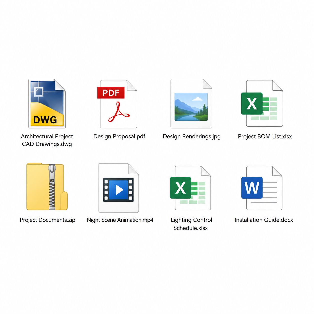
Count by fixture type, facade area, bridge section or project zone.
Confirm RGB, RGBW, pixel or custom channel mode before sizing outputs.
Calculate the actual DMX channel load from the approved fixture schedule.
Map output capacity, project zones and the physical installation sequence.
Select controller and node capacity with appropriate spare room for the project.
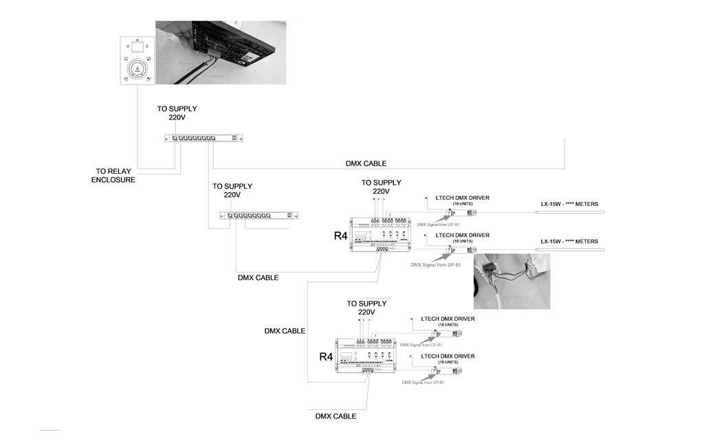
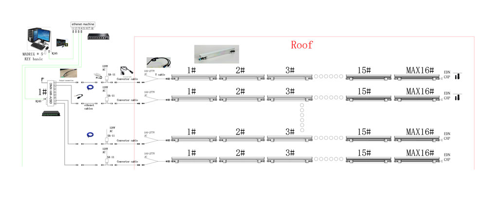
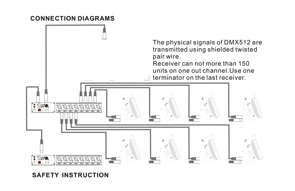
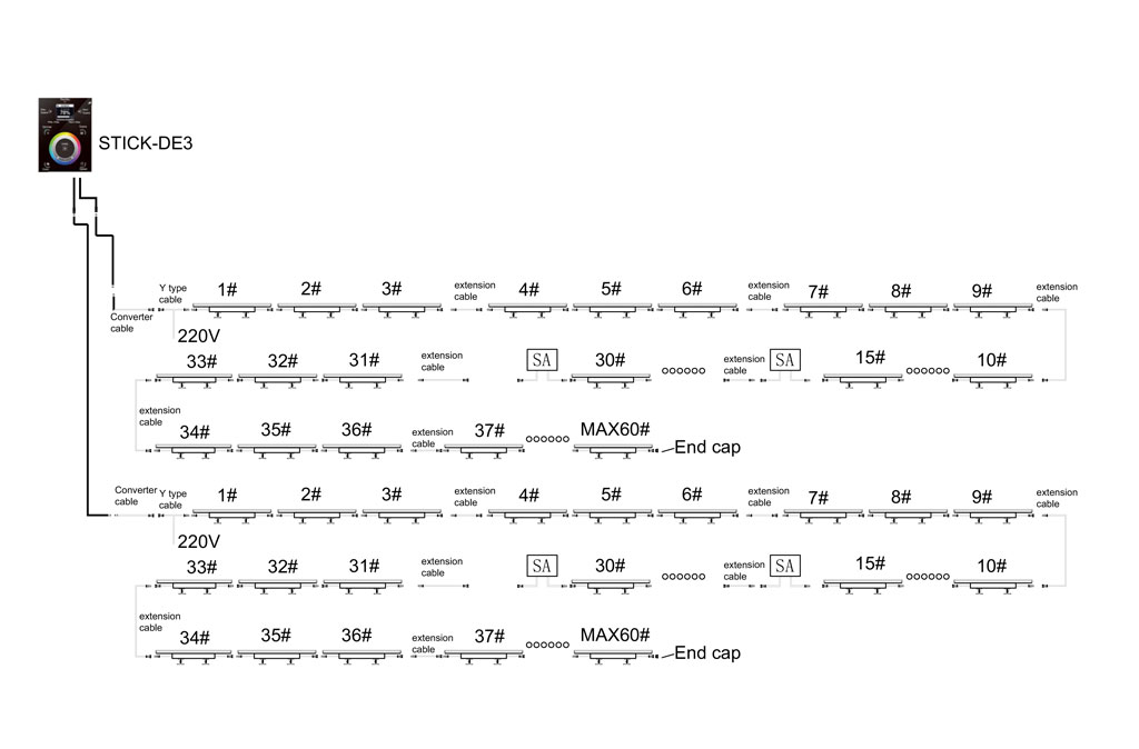
Shown diagrams are reference layouts. Final controller location, output count, accessories and cable routing follow the approved fixture schedule and site conditions.
We review channels per fixture, zones, standalone playback, wall-station needs, control distance, existing systems and required protocols before recommending MADRIX, Pharos, Nicolaudie/Sunlite or another compatible path.
Controller capacity, universes, output ports, distributed nodes and appropriate spare capacity are sized from the final fixture schedule and channel mode.
Based on the site layout, we can recommend practical controller/node locations to shorten difficult cable runs and keep the signal architecture easier to troubleshoot.
For suitable projects, we can issue a principle schematic showing the main controller, network path, nodes, DMX outputs, signal accessories, fixture runs and project-specific connection order.
We review Ethernet and DMX routing, selected equipment, physical distance, switch locations, isolation and whether amplification or fiber conversion is required.
If a building already has Pharos, MADRIX, Sunlite/Nicolaudie or another system, we review how the proposed TPK luminaires and addressing should fit that existing control environment.
TPK rule: if an item is required in the quotation, it should also appear on the control drawing.
Interface between luminaire wiring and XLR/DMX equipment where required.
Power-feed accessory selected according to the luminaire connection layout.
Used where the approved signal topology requires regeneration or distribution.
Project cable option for control-signal connections where specified.
Intermediate power-injection accessory for approved fixture runs.
Signal-entry cable selected to match the fixture and controller-side interface.
Alternative mid-run power-injection option used in selected connection layouts.
End-of-line termination accessory where the approved DMX wiring requires it.
Branch connector option for approved luminaire wiring layouts.
Review required luminaire certification such as ETL/cETL where applicable and identify documentation needed for the agreed project scope.
Confirm project voltage, including project-specific 120 V / 277 V requirements, and whether high-voltage or low-voltage fixture architecture is appropriate.
Review DMX512, RDM, Art-Net, sACN, DALI or other interfaces stated in the project documents and existing-control requirements.
Coordinate cable, connection, controller/node placement and environmental requirements with the intended outdoor installation.
Check relevant controller documentation and compatibility rather than relabeling third-party hardware as TPK-manufactured products.
Identify meaningful differences between the original specification and the proposed TPK luminaire/control package before the BOM is frozen.
The objective is not only to test an individual luminaire. Where the project scope requires it, we prepare the addressing and mapping logic, connect the agreed control chain and verify signal response and playback before shipment.
When the final channel mode, installation sequence and address schedule are confirmed, we can prepare the recommended address plan and pre-address fixtures where suitable.
Controller output, universe, fixture ID, installation position and start address can be organized so the software patch follows the same numbering logic as the physical installation.
For projects that require defined static colors, chase or other verification sequences, project-specific test content can be prepared for factory verification. Creative show design can be scoped separately.
A minimum control set can be used for mock-up verification where required. Applicable orders can include controller/node recognition, fixture response, power-cycle verification and a project-specific factory test record.
Depending on the project scope, the handover package can turn the control engineering into documents and files the installer can actually use on site.
Principle wiring, control topology, major signal components and project-specific connection logic.
Controllers or nodes supplied for the project plus the agreed signal accessories included in the shipment.
Fixture IDs, positions, universes, ports and DMX start addresses where applicable.
Project-specific test video or verification record for the agreed control configuration where applicable.
Relevant controller, patch, parameter or show files where they are part of the agreed scope.
Project-specific connection notes plus standard operating instructions for the selected control platform.
TPK provides remote commissioning and troubleshooting guidance for supported projects. Instead of replacing the controller first, we help the installation team narrow the problem down to the layer that is actually failing.
Remote support can include connection review, IP/network checks, software recognition, fixture patching, address verification and playback testing according to the agreed system scope.
Check signal chain, cable quality, splitter/amplifier status, connector wiring and connection order.
Check RGB/RGBW mode, channel order, fixture type and addressing.
Verify the address table and field replacement/re-addressing logic.
Check port-to-fixture mapping, patch order and actual installation sequence.
Isolate the fault by power, signal, address and output rather than replacing the whole controller.
Check IP settings, network path, switch power, device recognition and interface configuration.
Review topology, selected equipment, distributed nodes, switches, isolation, amplification or fiber architecture.
Check the actual accessory path against the principle drawing and approved connection order.
Confirm upload, storage, schedule and playback configuration after the laptop is removed.
Replace and re-address the fixture while keeping the existing controller and show file where the system design allows.
TPK manufactures the luminaires. Controller brands below are selected according to project requirements and remain products of their original manufacturers.
| Platform | Best fit | Typical TPK support | Official links |
|---|---|---|---|
| MADRIX | Pixel-heavy façades · media-driven effects · scalable DMX/eDMX | MADRIX 5 / KEY sizing · node selection · patching · address schedule · factory verification | |
| Pharos Designer | Permanent systems · standalone playback · distributed DMX/RDM | LPC/LPC X sizing · RIO G4 topology · Designer 2 review · fixture compatibility | |
| Nicolaudie / Sunlite | Standalone · wall-panel · multi-zone control | STICK-DE3 / DINA-DR1 selection · zone planning · eDMX/DMX · addressing · factory test |
MADRIX, Pharos and Nicolaudie are independent brands. References are for compatibility and project-selection purposes only and do not imply ownership, manufacturing origin or brand affiliation.
These references matter because control, signal accessories, fixture configuration and commissioning support were part of the project work — not because they are generic night-view photographs.
DMX512 | 12 Universes | Nicolaudie STICK-DE3
RGBW architectural facade lighting with DMX-controlled linear and wall-washer luminaires. TPK supported controller sizing, signal accessory planning, addressing logic and project commissioning preparation.
View project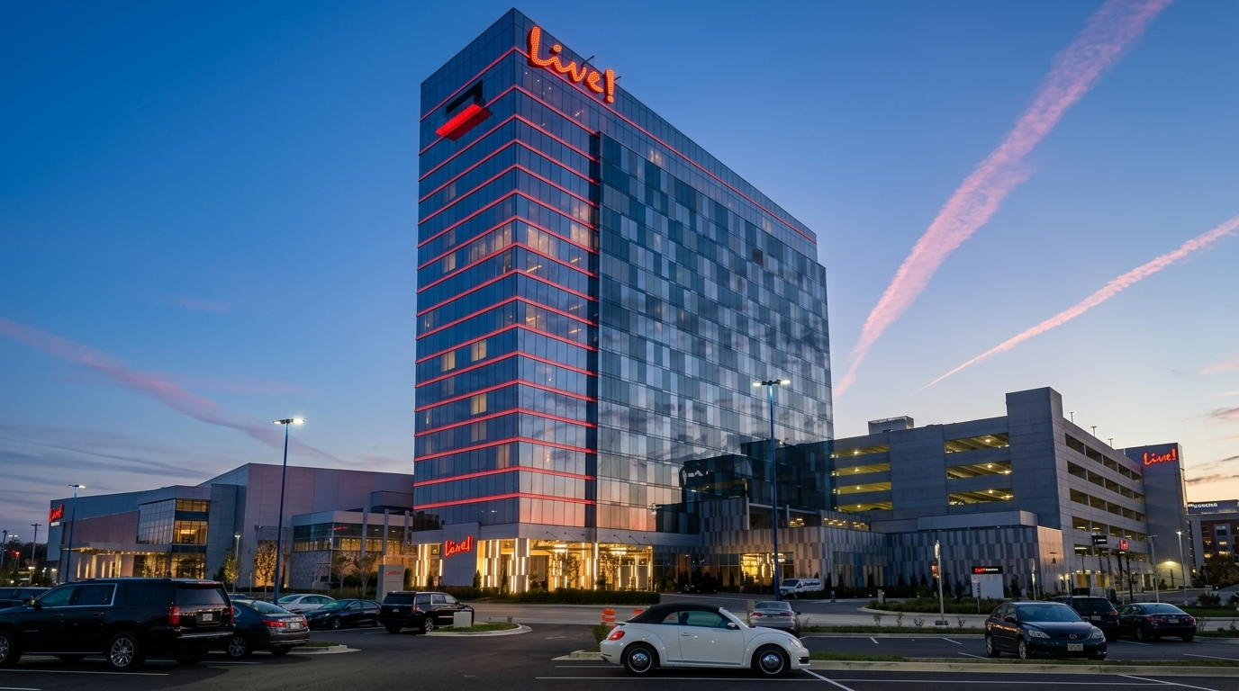
Pharos Control System | DMX Architectural Facade
Facade lighting project where Pharos control, fixture certification, project voltage, signal accessories and installation requirements were coordinated as one control-support package.
View project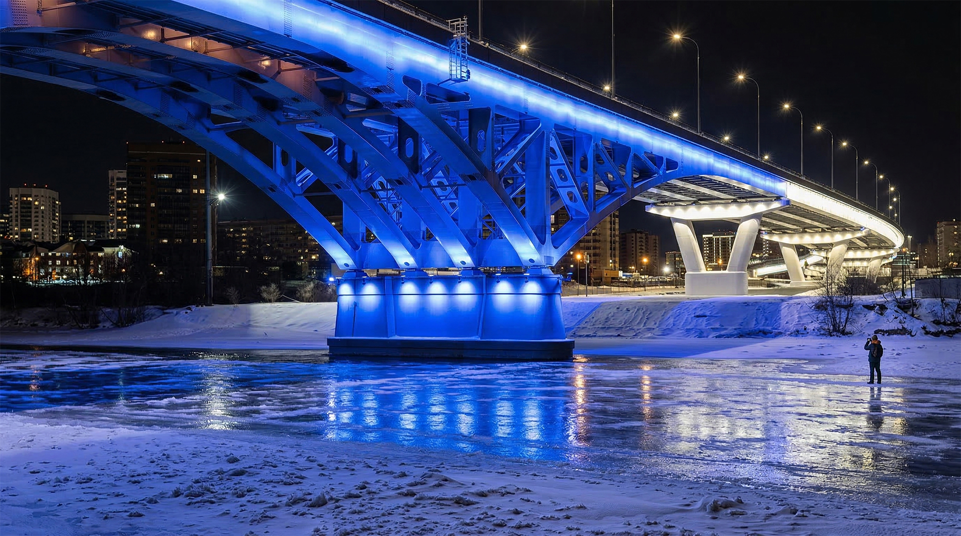
Fiber/eDMX | Pharos LPC | Long Distance Signal
Large outdoor bridge-lighting project where long-distance signal architecture, distributed control, fiber/eDMX planning and signal-path reliability were central to the system design.
View projectTPK-listed addressing tools, signal splitters and control accessories.
02Technical ResourcesSpecifications, catalogues, certificates and project-support downloads.
03Facade Lighting SolutionsArchitectural wall washer and linear-light solutions for building exteriors.
04Bridge Lighting SolutionsLighting systems for bridge structures, long runs and outdoor infrastructure.
Share the fixture schedule, control requirement, CAD/BOQ and any specified controller information. TPK can review the luminaire, signal, control and accessory requirements together and return a project-ready proposal for discussion.